hello guys..after a long time without any tutorial post from me,today i would like to post a tutorial on modeling a sport rim..this time it is a TE37 sport rim..
this tutorial will cover the modeling part..the unwrapping and textureing part will come later..
so first you will need a reference pic or a blueprint for the rim just like what i am using below

-Note that this rim has 6 identical spokes so i will not model all 6 individually.instead,i will model one and duplicate it.
-the first thing to do is to decide which spoke are we going to model.
-im going with this one
 -I will model the on in the region marked with red.
-After that,just open your maya and insert the rim pics as blueprint.
 -Just like above.
-to make it easier to model,make sure your rim is in the middle of the grid,horizontal and vertically so that the middle point of the rim is located on the 0,0,0 point of the system.
-next i rotate the pics to make sure the middle line of the spoke im modeling is located straight on top of the grid just like below.
 -after all of that is done,we can start modeling the rim.
-I usually start with a cylinder modelled on the middle of the rim.
 -Make sure the polycount of the cylinder is enough and make sure there are edges located on top of the partition line and middle line that you had drew on the rim pic.
-After that,delete the unwanted surface.on this case,delete the side and the back face of the cylinder and you will have something that looks like this.
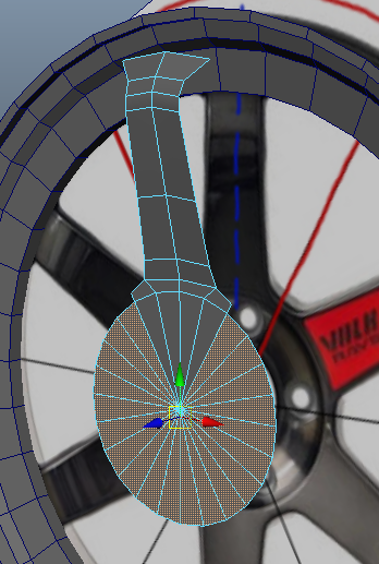
 -Now you can start modeling the spoke..grab the edges corresponding for the spoke in the image and extrude it..just follow the image and you will surely be okay.
-Here is what mine looks like.
 -Extrude it a little more for the bridge connecting the spoke and the ring.
 -Now its time to create the profile of the rim.
-Select the vertices just like below and push it outwards for creating a concave shaped rim.

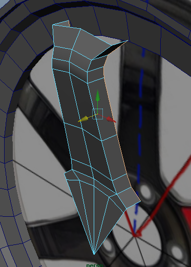
 -Next,its time to add a little more poly to the spoke..add edge loops and shape the spoke based on the blueprint.
 -As showned above,I added 3 more edge loops to smooth my spoke for better calculations.
-Lets pause the spoke for now.Time to add the lip or the ring for the rim.
-Create another cylinder and positioned it in the center of the grid just like the previous cylinder.

 -Adjust the edge count of the cylinder so that the edges overlapped the smaller cylinder just like in the pics above.
-This time also delete the side and rear faces of the cylinder.
 -Next extrude the faces of the cylinder and push and extrude and scale following the guide in the blueprint to create the profile of the rim’s ring.
-You should end up with something like this.

 -Now its time to delete the unused faces of the small cylinder.
 -As showned above,extrude the side edge of the spoke to make the thickness.
-I pushed the marked vertices down to help aligned the spoke edges with the ring edges just like showned below.
 -Next we are gonna combine the vertices of the spoke to the corresponding vertices of the ring.
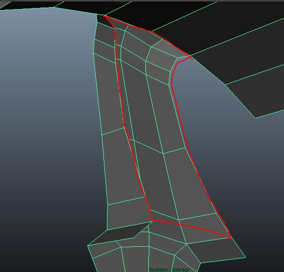
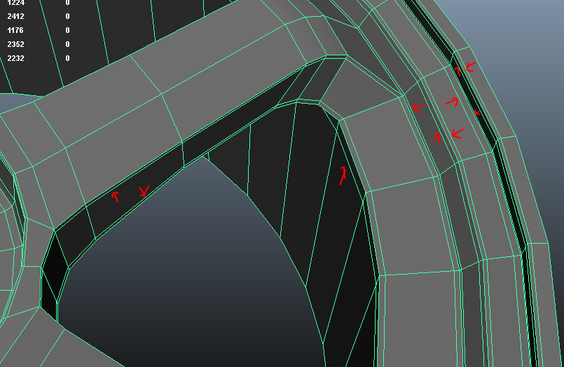
 -So,I am deleting the faces marked in red above and merge the vertices to the ring vertices.
 -But befor that you need to combine the ring and the spoke into one polysurface.
 -then merge the vertices.
 -There you go..next i move some vertices to smooth down the bridge.
 -Just like that.
-After that just delete the unused faces of the cylinder to have something that looks like below.

 -Now i hide my blueprint and turn the view around to the backside of the spoke.
-we will need to fill the gap of the backside of the spoke.
 -So that it looks like this.
 -Now its time to diplicate the spoke around..
-Use DUPLICATE SPECIAL and i have the setting just like below.
 -and execute it to have something like this.
 -There you go..but its not done yet..because the spokes is still seperated.
-combine all the spokes and sew the vertices on the edges below.
 -Now when you double click a face it should select all your rim faces.
-Next we are creating the center hole and the nut hole of the rim.
-Select the faces in the middle just like below and extrude it.
 -scale it and extrude it accordingly based on the blueprint,creating the profile of the centre hub of the rim.
-Mine looks like below.


 -Now if you press 3 on your maya it still doesnt look that good.
 -Now to make things better,we need to sharpened some edges a bit.
-I added edge loops like below to sharpen things a bit.

 -and you will have something like this
 -looks good isnt it?nope not yet..
-select the lips edges like below.
 -extrude it a bit and add edge loops here.
 -Let it be there for now. Next we will work on the nut hole.
-Create edge loops to support making the hole.
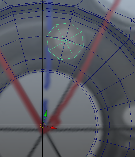
 -after that,create small cylinders with the size of the hole just like below.
 -After positioning it,we will use boolean to make the hole…select the cyinder and the rim and choose BOOLEAN>DIFFERENCE.
-and you should end up with something like below.
 -Also you will end up with a lot of floating vertices..and i mean A LOT.so clean up a bit and after that you will have a rim just like mine below

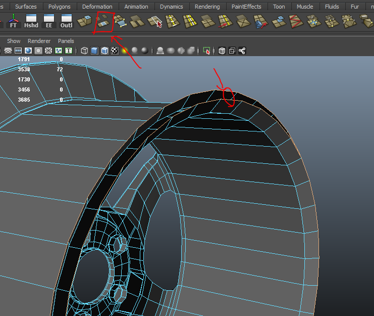
 -Next we will continue working on the lip we left before..select the edges and extrude it just like this.

 -Now you need to fill the gap of those two edge loop.
-select the two of them and bridge them.
 -And there goes your rim..its finished.

 -Thanks for viewing.any question feel free to ask me.


